This post will be about some reflections I had when reading about the frequency resource allocation in 5G NR. I will specifically discuss frequency resource allocation on DL since this is the area I’ve been reading about.
In addition to giving a short description of resource allocation in 5G NR, I set out to answer the following questions:
- Why are the nominal resource block group (RBG) sizes the values they are?
- Why are the non-nominal RBG sizes the values they are?
- How can we reason about the different combinations that can be encoded in resource allocation type 1?
If any of this sounds interesting, you might found the information below useful.
Resource allocation types
In 5G NR, there are two ways to describe frequency resource allocation in DL. The “frequency assignment” is part of the DCI, and is how the network tells the terminal what frequency resources will be used for PDSCH.
There are two ways to describe frequency resource allocations:
- Resource allocation type 0
- Resource allocation type 1
Resource allocation type 0
When using resource allocation type 0, the network tells the terminal the frequency resources to use by the way of a bitmap.
It is tempting to think that we could use 1 bit per resource block in the bitmap, but this approach doesn’t scale well if we want to keep our control data overhead as small as possible. In 5G NR, there are a maximum of 275 resource blocks in DL, and allocating 1 bit per resource block would be costly.
Instead, a tradeoff is reached: the number of bits is limited so that the DCI can remain small, but allocation resolution is reduced since 1 bit is used to represent a group of resource blocks (RBG) instead of uniquely representing a resource block.
The size of the RBG varies by bandwidth as described in TS 38.214
| Bandwidth Part Size | Configuration 1 | Configuration 2 |
|---|---|---|
| 1 – 36 | 2 | 4 |
| 37 - 72 | 4 | 8 |
| 73 - 144 | 8 | 16 |
| 145 - 275 | 16 | 16 |
The values in the table represent the “nominal” size of the RBG (denoted P).
Why these nominal RBG sizes?
Something that jumps out from the table is that RBG sizes are proportional to the size of the bandwidth - i.e. RBG sizes get bigger as bandwidth gets bigger. This makes sense given that if we were to use say size=2 for all bandwidths, larger bandwidths will have proportionally high number of RBGs which will mean a higher number of bits in the DCI to describe the frequency allocation.
If we want to keep the number of RBGs constant regardless of bandwidth, the RBG size must get bigger as bandwidth increases. If you divide the max bandwidth size of each group in the table by the RBG size, you get exactly that: a constant number of RBGs - between 17-18 for Configuration 1.
I believe this number was chosen to be compatible with resource allocation type 1 which is described in the next section. Frequency allocation type 1 has a specific number of combinations that can be represented. This number turns out to be 16 for the maximum bandwidth part size.
This is similar to the size seen in this allocation type, so both allocation types use roughly the same number of bits in the DCI.
So what are the “non-nominal” RBGs?
If there are nominal RBG sizes, it is safe to assume that there will also be “non-nominal” RBG sizes. It turns out that “non-nominal” RBGs are RBGs whose size are smaller than the nominal ones.
These RBGs are the first and last RBGs of the bandwidth part (BWP). Defined as follows in TS 38.214:
- the size of the first RBG is
- the size of the last RBG is
Why these non-nominal RBG sizes?
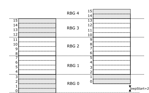
I found that this comes from the fact that RBG boundaries are kept aligned regardless of a shift in the start of the BWP (bwpStart). The RBGs are defined for a zero-shifted bwpStart, and any RBGs that belong to a non-zero shifted bwpStart are aligned to the zero-shifted bwpStart.

In the figure above, notice that for bwpStart=2, RBGs at both ends of the bandwidth part are smaller (shaded gray in the figure). These are two “non-nominal” RBG sizes. From the figure, it is clear that if alignment is to be kept, the RBGs at both ends of the BWP will have a different size - a non-nominal size - if the start of the BWP is shifted.
Resource allocation type 1
When using resource allocation type 1 the network tells the terminal a start frequency resource and a number of contiguous frequency resources to use.
This is different from type 0, wherein the terminal is given the resources to use by the way of a bitmap. Also different from type 0 is that in type 1, there is no longer a need
for RBGs. Instead, the precise starting resource block and the number of contiguously allocated resource blocks is signaled in the DCI. Both pieces of data (start and number) are encoded in a value called resource indication value (RIV).
How many combinations do we have for start resource block / number of resource blocks given a certain bandwidth?
To answer this question, I find it useful to think of a simple scenario.
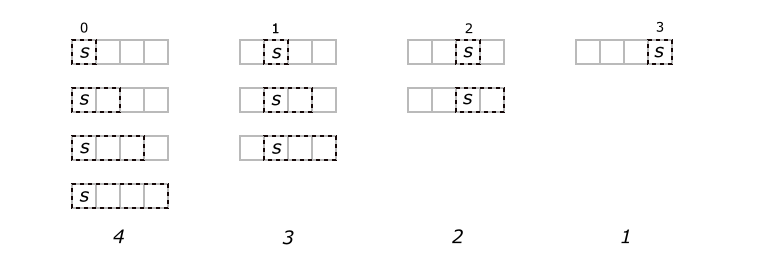
Suppose our bandwidth was equal to 4. If our start resource block is S, there are four such start resource blocks:
 For each of those start resource blocks S, we have a different number of resource blocks to use. This number is limited by the number of resource blocks ahead of the start resource block.
If S = 0, there four different allocation sizes (shown leftmost in the image below). If S = 1, there are three different allocation sized and so on.
 As can be seen in the image, in total we have 1 + 2 + 3 + 4 different possible configurations for our frequency allocation.
We can easily generalize this to say that given a bandwidth B there will be 1 + 2 + 3 … + (B - 1) + B possible different possible configurations.
Using the sum of natural numbers, this is equivalent to
The above tells us how many combinations would be possible, but how many bits will we need in the DCI?
We will need log2 number of bits (plus a ceil operator to get the next integer)
This is analogous to the formula found in TS 38.212,
where,
= The number of resource blocks in the bandwidth part
![]()